

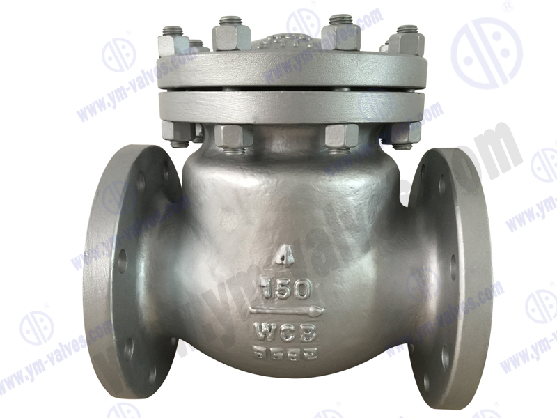
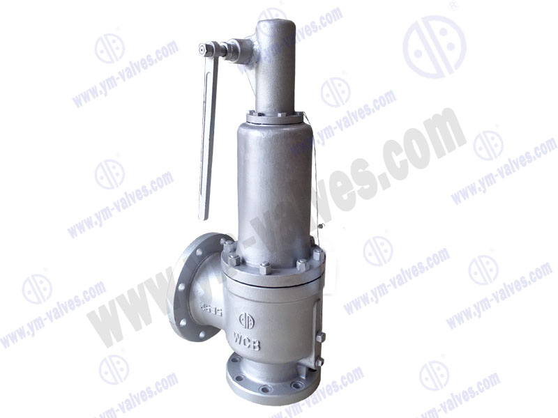
- Category
- Hot products
.jpg)
-
Abnormal pressure rise in the middle cavity of the gate valve
-
Abnormal pressure rise in gate valve cavity refers to a phenomenon in which, when the valve is closed or partially closed, the trapped medium expands due to heat or pressure buildup, causing the pressure in the valve cavity to rise significantly, potentially exceeding the system design pressure. This situation can pose serious safety hazards and equipment damage, requiring targeted protective measures.
1. Hazards of Abnormal Pressure Rise in Gate Valve Cavity
Valve Body Damage
Valve Body Rupture: When the cavity pressure exceeds the material strength limit, it may cause deformation or cracking of the valve body or bonnet.
Seal Failure: High pressure can compress the valve seat sealing surface, causing deformation of the metal sealing surface or tearing of soft sealing materials (such as PTFE), resulting in internal or external leakage.
Valve Stem Sticking: Pressure pushes the gate against the valve stem, increasing operating torque and even causing the stem to break.
Safety Risks
Media Leakage: Leakage of high-temperature, high-pressure media (such as steam or toxic gases) can cause fire, poisoning, or environmental pollution.
Valve Blowout: In extreme cases, broken bonnet bolts may cause the bonnet to pop out, resulting in personal injury or death.
System Failure
Impact on Upstream and Downstream Equipment: A sudden increase in the center chamber pressure may be transmitted to pipelines or connected equipment, leading to a chain reaction of system overpressure.
2. Common Causes of Abnormal Pressure Increase
Thermal Expansion of the Medium: For example, liquid media (water, oil) expand in volume upon heating in a closed center chamber, causing a sudden increase in pressure (liquid water increases its pressure by approximately 0.3 MPa for every 1°C increase in temperature).
Vaporization Effect: Liquid vaporizes at high temperatures (such as in boiler systems), expanding its volume hundreds of times.
Bidirectional Seal Design: The bidirectional seal of the gate disc of some gate valves completely seals the center chamber, exacerbating pressure buildup.
System Pressure Fluctuation: A sudden increase in upstream pressure (such as when a pump starts or stops) while the downstream pressure is closed.
3. Protective Measures
Structural Design Optimization
Center Chamber Pressure Relief Device: Add a pressure relief hole or an automatic pressure relief valve (such as a spring-loaded safety valve) to the valve body to automatically release pressure when the pressure exceeds the set value. Perforated Gate: Small holes (such as balancing holes) are designed in the gate to allow a small amount of media to pass through to equalize pressure. However, be aware of the media used (not suitable for applications with stringent sealing requirements).
Bonnet Reinforcement: Use high-strength bolts or a thickened bonnet to increase pressure-bearing capacity.
Material and Process Control
Pressure-Resistant Materials: The valve body is constructed of high-strength materials (such as ASTM A216 WCB upgraded to A352 LCC low-temperature steel or A351 CF8M stainless steel).
Heat Treatment: Eliminate casting residual stresses and improve pressure resistance.
Operation and Maintenance
Avoid half-open valves: Pressure buildup in the center chamber is more likely when the valve is half-open; the valve should be fully open or fully closed.
Regularly inspect pressure relief devices: Ensure the pressure relief valve and exhaust valve are functioning properly.
System Pressure Monitoring: Install a pressure gauge or sensor to monitor the center chamber pressure in real time.
Special Operations: High-Temperature Media: Use a jacket for insulation or heat dissipation to minimize expansion caused by temperature rise. Low temperature medium: prevent residual liquid from vaporizing after the valve is closed (such as LNG valves need precooling operation).
4. Typical application examples
Power station main steam gate valve: usually equipped with a middle cavity pressure relief valve to prevent thermal shock when the boiler is started and stopped.
Oil pipeline gate valve: adopts an open-hole gate design to balance the pressure fluctuations in crude oil transportation.
Chemical system: select double-disc gate valves or parallel gate valves to reduce the risk of middle cavity closure.
5. Standard specification reference
API 600/API 6D: requires gate valve design to consider abnormal pressure rise protection.
ASME B16.34: puts forward clear grade requirements for the pressure bearing capacity of the valve body.
ISO 5208: The sealing performance test includes verification of abnormal pressure conditions.
Through reasonable design, selection and operation, the risk of abnormal pressure rise in the middle cavity of the gate valve can be effectively avoided to ensure safe and stable operation of the system. For critical conditions, it is recommended to consult a professional valve manufacturer for customized solution design.