- Category
- Hot products
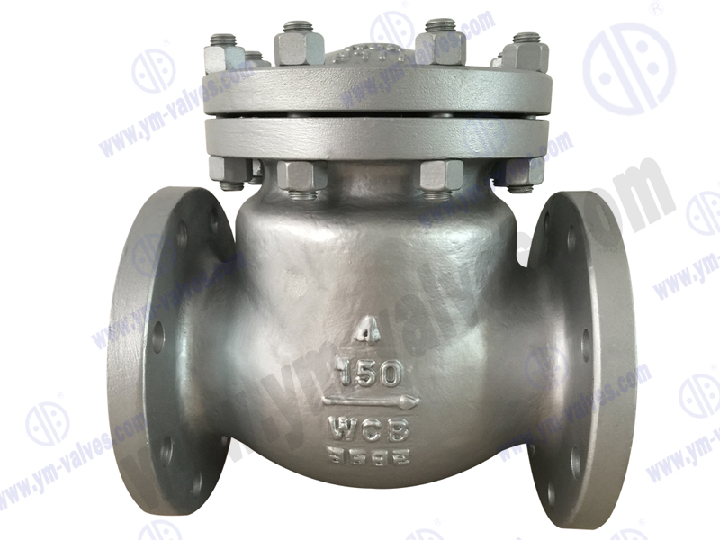
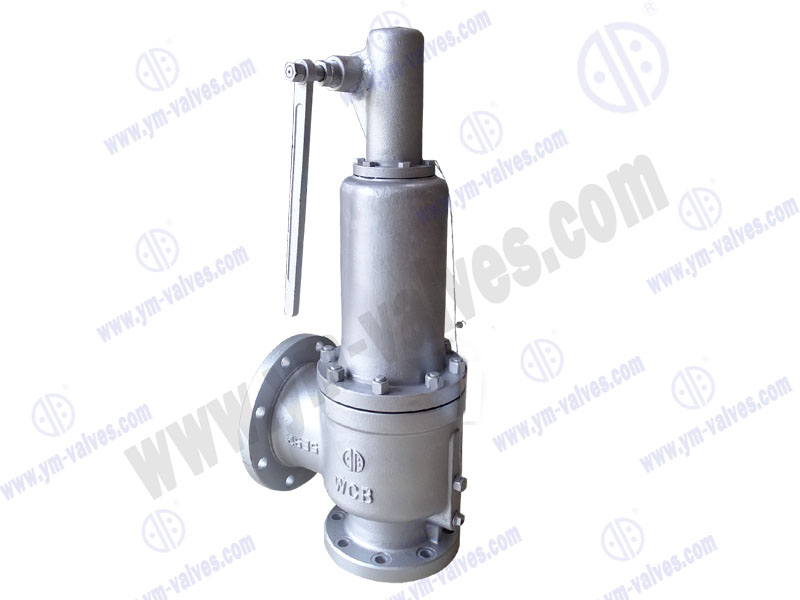
Position: Home > Products > Forged steel valve series
.jpg)
.jpg)
.jpg)
.jpg)
.jpg)
We're here to help:
Easy ways to get the answers you need.
.jpg)
| WORKING PRESSURE RATING | NPS | DN | STANDARD DESIGN TYPE | A-RF (mm) | A-RJ (mm) | B (in) | C (in) | H (in) |
| ASME 150 | 1/2" | S1 | 108 | 4.25 | N.A. | 0.39 | 3.5 | 17.7 |
| 3/4" | S1 | 117.5 | 4.63 | N.A. | 0.55 | 3.5 | 17.7 | |
| 1" | S1 | 127 | 5 | N.A. | 0.66 | 3.8 | 18.9 | |
| 1-1/2" | S1 | 165 | 6.5 | 140 | 1.14 | 5.4 | 20.7 | |
| 2" | S1 | 203 | 7.99 | 178 | 1.38 | 6.8 | 21.8 | |
| 1/2" | S1 | 152.5 | 6 | 163.5 | 0.35 | 3.5 | 17.7 | |
| 3/4" | S1 | 178 | 7.01 | 190.5 | 0.51 | 3.5 | 18 | |
| ASME 300 | 1" | S1 | 203 | 7.99 | 216 | 0.66 | 3.8 | 18.9 |
| 1-1/2" | S1 | 229 | 9.02 | 241 | 1.14 | 5.4 | 19.6 | |
| 2" | S1 | 267 | 10.51 | 282.5 | 1.38 | 6.8 | 22.6 | |
| 1/2" | S1 | 165 | 6.5 | 163.5 | 0.35 | 3.5 | 18 | |
| 3/4" | S1 | 191 | 7.52 | 190.5 | 0.51 | 3.5 | 17 | |
| ASME 600 | 1" | S1 | 216 | 8.5 | 241 | 0.66 | 3.8 | 19.2 |
| 1-1/2" | S1 | 241 | 9.49 | 216 | 1.14 | 5.4 | 20.6 | |
| 2" | S1 | 292 | 11.5 | 295 | 1.38 | 6.8 | 17.6 | |
| 1/2" | S1 | 216 | 8.5 | 216 | 0.35 | 3.5 | 22.5 | |
| 3/4" | S1 | 229 | 9.02 | 229 | 0.55 | 3.8 | 19.1 | |
| ASME 1500 | 1" | S1 | 254 | 10 | 254 | 0.55 | 5.4 | 20.6 |
| 1-1/2" | S1 | 305 | 12.01 | 305 | 1.02 | 6.8 | 22.4 | |
| 2" | S1 | 368 | 14.49 | 371.5 | 1.34 | 6.8 | 24 | |
| 1/2" | S3 | 108 | 4.25 | N.A. | 0.51 | 3.5 | 17 | |
| 3/4" | S1 | 117.5 | 4.63 | N.A. | 0.69 | 3.8 | 19.6 | |
| ASME 150 | 1" | S1 | 127 | 5 | N.A. | 0.89 | 5.4 | 20.1 |
| 1-1/2" | S1 | 165 | 6.5 | 178 | 1.38 | 6.8 | 22.4 | |
| 2" | S1 | 203 | 7.99 | 216 | 1.77 | 6.8 | 23.2 | |
| 1/2" | S1 | 152.5 | 6 | 163.5 | 0.51 | 3.5 | 17.7 | |
| 3/4" | S1 | 178 | 7.01 | 190.5 | 0.69 | 3.8 | 19.1 | |
| ASME 300 | 1" | S1 | 203 | 7.99 | 216 | 0.89 | 5.4 | 20.6 |
| 1-1/2" | S1 | 229 | 9.02 | 241 | 1.38 | 6.8 | 22.4 | |
| 2" | S1 | 267 | 10.51 | 282.5 | 1.77 | 6.8 | 23.2 | |
| 1/2" | S1 | 165 | 6.5 | 163.5 | 0.51 | 3.5 | 17.7 | |
| 3/4" | S1 | 191 | 7.52 | 190.5 | 0.69 | 3.8 | 19.1 | |
| ASME 600 | 1" | S1 | 216 | 8.5 | 241 | 0.89 | 5.4 | 20.6 |
| 1-1/2" | S1 | 241 | 9.49 | 216 | 1.38 | 6.8 | 22.4 | |
| 2" | S1 | 292 | 11.5 | 295 | 1.77 | 6.8 | 24.6 | |
| 1/2" | S1 | 216 | 8.5 | 216 | 0.47 | 3.8 | 19.4 | |
| 3/4" | S1 | 229 | 9.02 | 229 | 0.57 | 5.4 | 21 | |
| ASME 1500 | 1" | S1 | 254 | 10 | 254 | 0.75 | 6.8 | 21.6 |
| 1-1/2" | S1 | 305 | 12.01 | 305 | 1.22 | 6.8 | 24.6 | |
| 2" | S1 | 368 | 14.49 | 371.5 | 1.5 | 5.4 | 28.3 | |
| 1/2" | S2 | 264 | 10.39 | 264 | 0.43 | 9.2 | 22.2 | |
| 3/4" | S2 | 264 | 10.39 | 264 | 0.57 | 5.4 | 22.2 | |
| ASME 2500 | 1" | S2 | 308 | 12.13 | 308 | 0.75 | 6.8 | 23.8 |
| 1-1/2" | S2 | 384 | 15.12 | 387 | 1.1 | 9.2 | 27.7 | |
| 2" | S2 | 451 | 17.76 | 454 | 1.5 | 12.6 | 28.1 |
.jpg)