- Category
- Hot products
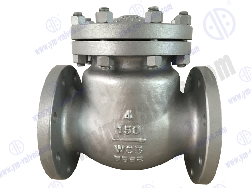
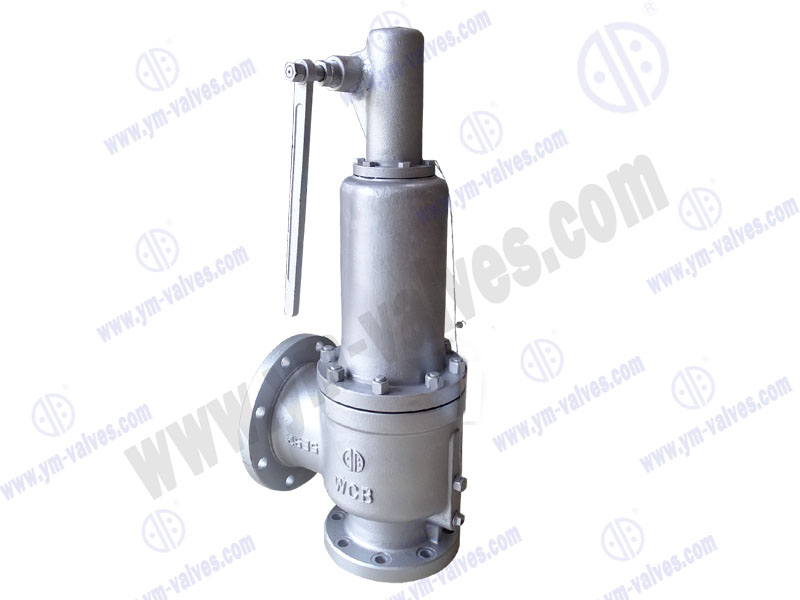
Position: Home > Products > Forged steel valve series
.jpg)
.jpg)
.jpg)
.jpg)
.jpg)
We're here to help:
Easy ways to get the answers you need.
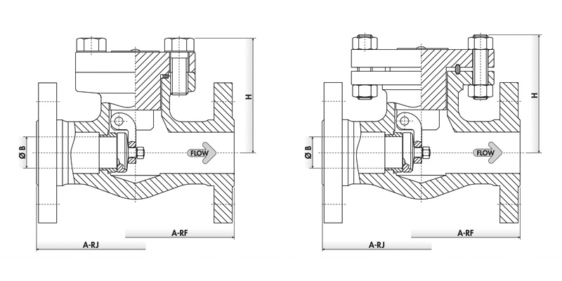
| WORKING PRESSURE RATING | NPS | STANDARD DESIGN TYPE | A - RF(in) | A - RJ(in) | B(in) | H(in) | FIGURE |
| ASME 150 | 1/2" | S1 | 4.25 | N.A. | 0.38 | 3 | L1 - 603 |
| 3/4" | S1 | 4.63 | N.A. | 0.55 | 3 | L1 - 604 | |
| 1" | S1 | 5 | 5.51 | 0.69 | 3.3 | L1 - 605 | |
| 1 - 1/2" | S1 | 6.5 | 7.01 | 1.16 | 4.3 | L1 - 607 | |
| 2" | S1 | 7.99 | 8.5 | 1.44 | 4.9 | L1 - 608 | |
| ASME 300 | 1/2" | S1 | 6 | N.A. | 0.38 | 3 | L3 - 603 |
| 3/4" | S1 | 7.01 | 7.01 | 0.55 | 3.1 | L3 - 604 | |
| 1" | S1 | 8.5 | 8.5 | 0.69 | 3.5 | L3 - 605 | |
| 1 - 1/2" | S1 | 9.49 | 10 | 1.16 | 4.5 | L3 - 607 | |
| 2" | S1 | 10.51 | 11.14 | 1.44 | 5.1 | L3 - 608 | |
| ASME 600 | 1/2" | S1 | 6.5 | 6.42 | 0.38 | 2.8 | L6 - 603 |
| 3/4" | S1 | 7.52 | 7.52 | 0.55 | 3.1 | L6 - 604 | |
| 1" | S1 | 8.5 | 8.5 | 0.69 | 3.3 | L6 - 605 | |
| 1 - 1/2" | S1 | 9.49 | 9.49 | 1.16 | 4.5 | L6 - 607 | |
| 2" | S1 | 11.5 | 11.61 | 1.44 | 5.1 | L6 - 608 | |
| ASME 150 | 1/2" | S1 | 4.25 | N.A. | 0.55 | 3.3 | L1 - 604 |
| 3/4" | S1 | 4.61 | N.A. | 0.71 | 3.3 | L1 - 604 | |
| 1" | S1 | 5 | 5.51 | 0.94 | 3.9 | L1 - 605 | |
| 1 - 1/2" | S1 | 6.5 | 7.01 | 1.44 | 4.9 | L1 - 607 | |
| 2" | S1 | 7.99 | 8.5 | 1.89 | 5.5 | L1 - 608 | |
| ASME 300 | 1/2" | S1 | 6 | N.A. | 0.55 | 3 | L3 - 604 |
| 3/4" | S1 | 7.01 | 7.01 | 0.71 | 3.5 | L3 - 604 | |
| 1" | S1 | 8.5 | 9.02 | 0.94 | 3.9 | L3 - 605 | |
| 1 - 1/2" | S1 | 9.49 | 10 | 1.44 | 4.7 | L3 - 607 | |
| 2" | S1 | 10.51 | 11.14 | 1.89 | 5.9 | L3 - 608 | |
| ASME 600 | 1/2" | S1 | 6.5 | 6.42 | 0.55 | 3 | L6 - 603 |
| 3/4" | S1 | 7.52 | 7.52 | 0.71 | 3.5 | L6 - 604 | |
| 1" | S1 | 8.5 | 8.5 | 0.94 | 3.9 | L6 - 605 | |
| 1 - 1/2" | S1 | 9.49 | 9.49 | 1.44 | 4.7 | L6 - 607 | |
| 2" | S1 | 11.5 | 11.61 | 1.89 | 5.9 | L6 - 608 | |
| ASME 1500 | 1/2" | S1 | 8.5 | 8.5 | 0.55 | 4.1 | 15F 603 |
| 3/4" | S1 | 9.02 | 9.02 | 0.71 | 4.9 | 15F 604 | |
| 1" | S1 | 10 | 10 | 0.94 | 5.3 | 15F 605 | |
| 1 - 1/2" | S1 | 12.01 | 12.01 | 1.44 | 6.1 | 15F 607 | |
| 2" | S1 | 14.49 | 14.61 | 1.89 | 7.7 | 15F 608 |
.jpg)