- Category
- Hot products
Position: Home > Products > Knife Gate Valve
We're here to help:
Easy ways to get the answers you need.
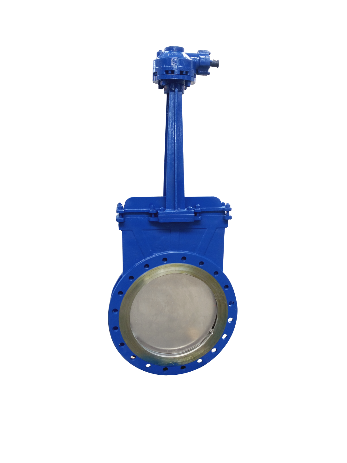
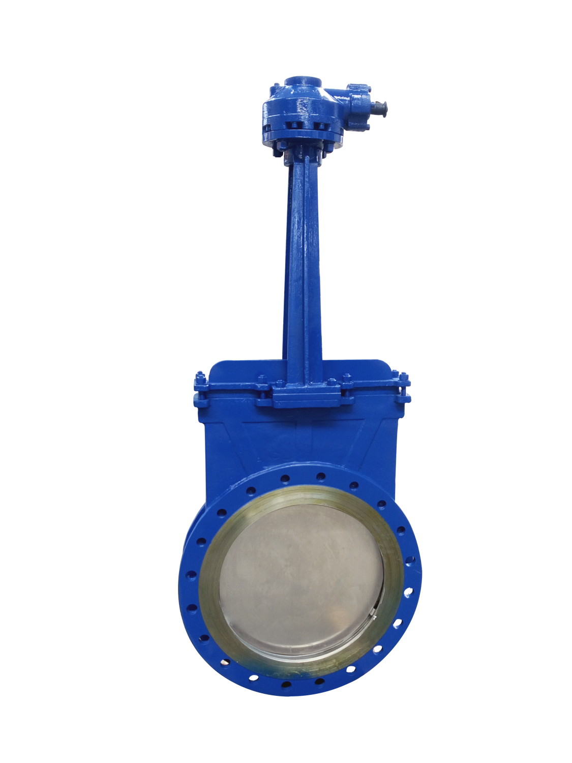
The knife gate valve produced by Yuming Valve Group Co., Ltd. is widely used in coal, filter residue slurry, waste water, mud, dirt, paper pulp, ash residue slurry, etc. Knife gate valve, also known as knife gate valve, is a knife-type slurry valve. Its opening and closing part is a gate. The movement direction of the gate is perpendicular to the direction of the fluid. The medium is cut by a blade-shaped gate that can cut fiber materials. The gate has Two sealing surfaces, the most commonly used mode gate valve, the two sealing surfaces form a wedge, and the wedge angle varies with the valve parameters, usually 50, the wedge knife gate valve gate can be made into a whole, called a rigid gate; Can also be made into a gate that can produce a small amount of deformation to improve its manufacturability and make up for the deviation of the sealing surface angle during processing. This kind of gate is called an elastic gate. The valve body does not actually have a cavity, and the gate moves up and down in the side guide groove, and is pressed against the valve seat by the lug at the bottom. If you need to achieve a higher medium tightness, you can use an O-shaped seat Two-way seal. The knife gate valve has a small installation space, low working pressure, difficult to accumulate debris, and low price.
Drive Method
Manual, sprocket, electric, pneumatic, hydraulic, bevel gear, electronically controlled hydraulic and gas hydraulic drive. Knife gate valve shape: bright rod and dark rod. Knife gate valve material: cast iron, cast steel, carbon steel, stainless steel, fluorine lining, etc. Knife gate valve seal: hard seal, soft seal, single side seal, double side seal and other material seals.
The ultra-thin knife gate valve completely solves the large flow resistance of ordinary gate valves, flat gate valves, ball valves, globe valves, regulating valves, butterfly valves and other valves due to its small size, small flow resistance, light weight, easy installation and easy disassembly. , Heavy weight, difficult installation, large area and other difficult problems. After the appearance of knife gate valves, a large number of general cut-off valves and regulating valves have been replaced. As of today, the largest amount of knife gate valves in the world is the United States and Japan.
Product Performance
1. Valve control can do local and remote control, and can also realize remote position display and remote centralized control according to user requirements.
2. Light weight: the body is made of carbon steel, the weight is reduced by about 20% -30% compared with the weight of the traditional gate valve, and the installation and maintenance are convenient.
3. The use of the valve can improve the closing and sealing performance of the conveying pipeline system, prevent leakage to the maximum extent, and play a positive role in improving production efficiency and protecting the environment.
4. The sealing surface is made of highly wear-resistant and corrosion-resistant ceramic materials, using inlay technology, high corrosion resistance and good wear resistance, so that the valve life is long, and the cost performance is 10 times higher than ordinary valves.
Features
1. The lifting type sealing surface of the gate can scrape off the adhesion on the sealing surface and automatically clean up the debris.
2. The stainless steel gate can prevent seal leakage caused by corrosion.
3. The hard all-gold sealing surface can ensure the sealing wear resistance and requirements.
4. There is no groove on the sealing surface of the valve body, and no deposit is generated, which can ensure flexible opening.
5. Short structure length can save raw materials, install space and effectively support pipeline strength.
6. The scientific upper seal stuffing box design makes the upper seal safe and effective and durable.
7. The triangular bracket saves raw materials and guarantees the required mechanical properties.
8. The guide block on the valve body allows the gate to move correctly, and the four squeeze blocks ensure the gate is effectively sealed.
9. The valve body rib design improves the strength of the valve body.
10. The stainless steel stem is durable and the double-headed bolt makes opening and closing more quickly.
11. The drive mechanism can be selected at will.
12. With a caliber of over 150, a fully enclosed structure is used to effectively open and prevent leakage.
13. Fluorine rubber sealing surface can achieve the sealing effect and increase the use temperature.
14. The rubber sealing surface is directly vulcanized in the valve body without falling off.
Installation and use instructions
1. Before installing the knife gate valve, it is necessary to check the valve cavity and the sealing surface, etc., no dirt or sand is allowed to adhere;
2. The bolts at each connecting part should be tightened evenly;
3. Check the packing parts to be tight, not only to ensure the sealing of the packing, but also to ensure the flexible opening of the gate;
4. Before installing the valve, the user must check the valve model, connection size and pay attention to the flow direction of the medium to ensure consistency with the valve requirements;
5. When installing the valve, the user must reserve the necessary space for the valve drive;
6. The wiring of the driving device must be carried out according to the circuit diagram;
7. The knife gate valve must be maintained regularly, and no collision or squeezing is allowed, so as not to affect the seal.
Use and Maintenance
1. The handwheel, handle and transmission mechanism are not allowed to be used for lifting, and collision is strictly prohibited.
2. The double gate valve should be installed vertically (ie, the stem is in the vertical position and the handwheel is at the top).
3. The gate valve with a bypass valve should be opened before opening (to balance the pressure difference between the inlet and outlet and reduce the opening force).
4. The gate valve with transmission mechanism shall be installed in accordance with the provisions of the product instruction manual.
5. If the valve is used frequently, lubricate it at least once a month.
The main shape and connection dimensions
|
Nominal diameter |
The main dimensions and connection dimensions |
|||||||
|
L |
D |
D1 |
D2 |
b |
Z-d |
H |
D0 |
|
|
PZ73X/H-10C |
||||||||
|
50 |
50 |
160 |
125 |
100 |
16-3 |
4-Φ18 |
285 |
180 |
|
65 |
50 |
180 |
145 |
120 |
18-3 |
4-Φ18 |
298 |
180 |
|
80 |
50 |
195 |
160 |
135 |
20-3 |
8-Φ18 |
315 |
220 |
|
100 |
50 |
215 |
180 |
155 |
20-3 |
8-Φ18 |
365 |
220 |
|
125 |
50 |
245 |
210 |
185 |
22-3 |
8-Φ18 |
400 |
230 |
|
150 |
60 |
280 |
240 |
210 |
24-3 |
8-Φ23 |
475 |
280 |
|
200 |
60 |
335 |
295 |
265 |
26-3 |
12-Φ23 |
540 |
360 |
|
250 |
70 |
405 |
355 |
320 |
30-3 |
12-Φ25 |
630 |
360 |
|
300 |
80 |
460 |
410 |
375 |
30-3 |
12-Φ25 |
780 |
400 |
|
350 |
90 |
520 |
470 |
435 |
34-4 |
16-Φ25 |
885 |
400 |
|
400 |
100 |
580 |
525 |
485 |
36-4 |
16-Φ30 |
990 |
400 |
|
450 |
120 |
640 |
585 |
545 |
40-4 |
20-Φ30 |
1100 |
530 |
|
500 |
130 |
705 |
650 |
608 |
44-4 |
20-Φ34 |
1200 |
530 |
|
600 |
140 |
840 |
770 |
718 |
48-5 |
20-Φ36 |
1450 |
600 |
|
700 |
165 |
910 |
840 |
788 |
50-5 |
24-Φ41 |
1700 |
600 |
|
800 |
190 |
1020 |
950 |
898 |
52-5 |
24-Φ41 |
2000 |
680 |
|
900 |
203 |
1120 |
1050 |
998 |
54-5 |
28-Φ41 |
2300 |
680 |
|
PZ73X/H-16C |
||||||||
|
50 |
50 |
160 |
125 |
100 |
20-3 |
4-Φ18 |
285 |
180 |
|
65 |
50 |
180 |
145 |
120 |
22-3 |
8-Φ18 |
298 |
180 |
|
80 |
50 |
195 |
160 |
135 |
22-3 |
8-Φ18 |
315 |
220 |
|
100 |
50 |
230 |
190 |
160 |
24-3 |
8-Φ23 |
365 |
220 |
|
125 |
50 |
270 |
220 |
188 |
28-3 |
8-Φ25 |
400 |
230 |
|
150 |
60 |
300 |
250 |
218 |
30-3 |
8-Φ25 |
475 |
280 |
|
200 |
60 |
360 |
310 |
278 |
34-3 |
12-Φ25 |
540 |
360 |
|
250 |
70 |
425 |
370 |
332 |
36-3 |
12-Φ30 |
630 |
360 |
|
300 |
80 |
485 |
430 |
390 |
40-4 |
16-Φ30 |
780 |
400 |
|
350 |
90 |
550 |
490 |
448 |
44-4 |
16-Φ34 |
885 |
400 |
|
400 |
100 |
610 |
550 |
505 |
48-4 |
16-Φ34 |
990 |
400 |
|
450 |
120 |
640 |
585 |
545 |
40-4 |
20-Φ30 |
1100 |
530 |
|
500 |
130 |
705 |
650 |
608 |
44-4 |
20-Φ34 |
1200 |
530 |
|
600 |
140 |
840 |
770 |
718 |
48-5 |
20-Φ36 |
1450 |
600 |
|
700 |
165 |
910 |
840 |
788 |
50-5 |
24-Φ41 |
1700 |
600 |
|
800 |
190 |
1020 |
950 |
898 |
52-5 |
24-Φ41 |
2000 |
680 |
|
900 |
203 |
1120 |
1050 |
998 |
54-5 |
28-Φ41 |
2300 |
680 |
Structure picture
.png)

.jpg)